
From John Pursell
I use Atlas switch machines on my layout. They’re reasonably priced, reliable, and available just about everywhere. I’ve even gotten used to the “buzz-clack” sound as one of them operates. What I’ve never gotten used to, though, is the big, honkin’ piece of black plastic that houses the solenoid. It lays right by the track and, in my opinion, bears no resemblance to anything prototypical. Because of this, I’ve devised ways to hide or disguise them.
I am aware of Atlas’s switch machines for “under table” mounting. I’ve used them in the past and they work well. But as my age advances and bad knees become more of a fact of life, I want to make as few trips as possible under my layout. I’ve decided to keep switch machines above ground, so to speak. I also know that Atlas includes a little piece of black plastic that allows you to mount the machine a bit further away, but even that’s not far enough for me. I prefer to have at least 3 to 4 inches between a turnout and the machine to allow for my coverings.
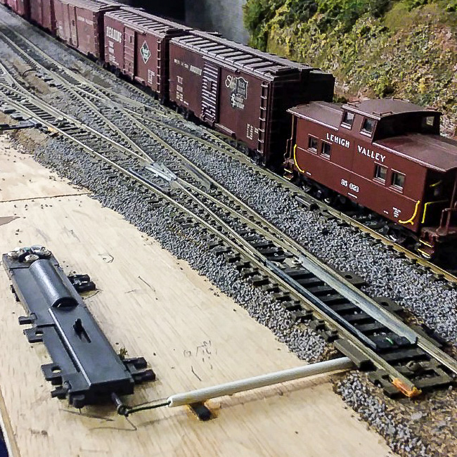
The first thing I do is work out a way to mount the machine at least a few inches away from the turnout and create the connection. When mounting them in this way, Atlas’s “left/right hand” switch machine designations do not matter because those cast-on track connections won’t be used.
My method uses a piece of green florist wire that is about 3/4 inch longer than the distance between the center of the turnout’s points and my Atlas switch machine throw bar’s location. First I measure 3/8 inch from one end of the wire and bend it up 90 degrees. Then I measure 1/8 inch from the tip on that bent end and bend it another 90 degrees, perpendicular to the first bend. Fit it into the hole on the turnout’s throw-bar. It should now extend, perpendicular to the track section, underneath the throw-bar. I do this before I mount the turnout on the roadbed.
Trim the roadbed under the throw-bar to allow the wire to freely move under the points. Note that the wire must also lay flat on top of the throw-bar so a passing coupler trip pin doesn’t get snagged.
It may take some trial and error to get this right. I use code 100 track and the measurements for bending could be different for different codes of rail or other manufacturer’s track. The measurements above are estimated. Florist wire is inexpensive. If it’s not correct, I toss it and do another.
Next, with the wire protruding out from the turnout to where the machine mounting spot will be I run the wire through a length of plastic tube that will fit between the roadbed and the machine. This allows me to cover the connection, preventing scenic material and adhesives form interfering with its movement. At the switch machine, the wire is bent around the actuating lever and squeezed down using pliers to reduce any play.
Holding the switch machine in it’s mounting spot, I check to see if everything works. In general, I keep the switch machine and turnout parallel to one another. When it functions smoothly, I permanently attach the switch machine and turnout with adhesive caulk. This will hold it, more or less, permanently. Since caulk always retains some resiliency, I’ll be able to replace it (with perhaps some small effort) if necessary. On occasion, I’ve mounted the machine on a small piece of cork roadbed, which puts it at the same height as the turnout. Using this method allows me to run a longer actuating (floral) wire under an adjacent track inside the plastic tube.
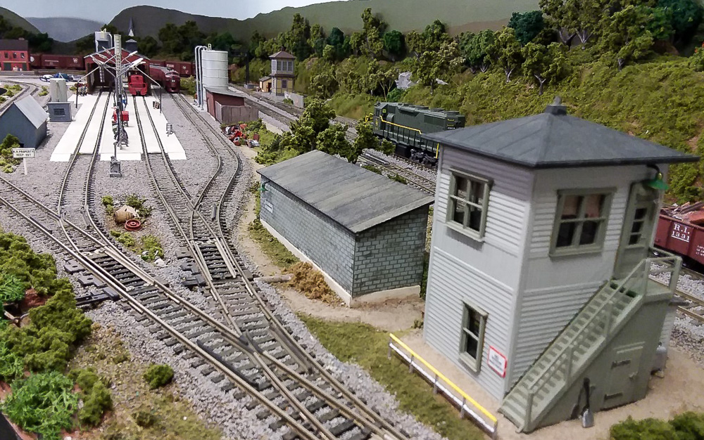
Disguising the machine consists of multiple methods. All of this should work for other types of switch machines. One advantage of Atlas machines is they are fairly flat. This helps with hiding them. The accompanying photo shows several of the ways I’ve done this. A small building with a slot for the wire to go through can be whipped up in minutes. Leave the building loose for adjustments or repairs. I also hide them behind trees or ground foam bushes. If going this route, I cover the actuator pin opening in the machine while gluing, painting, or working with foam. I’ve can also made a small knoll out of carved foam to fit over the machine, covering the knoll with ground foam, grass, and weeds to blend in the rest of the scenery. If this knoll is by an industrial area, I would cover it with mixed, small pieces of junk to resemble a scrap pile. Since the machines are flat, I’ve also hidden them behind fences, extend an inch or two beyond the edges of the machine, completely hiding them. Fences are often good if there’s just no room for anything else.
Above is the Easton engine terminal on my Lehigh Valley RR, where six Atlas switch machines are hidden. Clockwise from the left: #1 inside the gray shed, #2 inside the red shed, #3 behind the hillside, #4 behind the bushes, #5 behind the block shed and #6 behind the shrubs across from the block building.
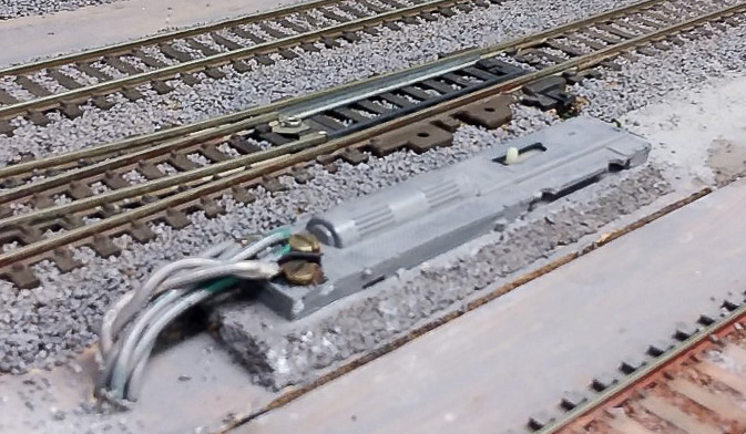
However, there are “worst case” scenarios. What if there’s simply no space for mounting the switch machine other than right by the track as Atlas intended? If I can’t hide it, I camouflage it. This is easily done by painting the machine (below) the same color as the ballast, making it much less noticeable. Oddly enough, over the years I’ve met many modelers who have simply never thought that you could paint the switch machine. As long as paint doesn’t get into the operating area it works fine. Depending on the surrounding scenery, I recommend gluing a few small pieces of foam on the sides to help the machine blend in better.
So that’s how I do it. It’s not difficult and allows me to keep using my preferred brand of switch machine. Try it and see if you like it. I assure you, your back and your knees will thank you!
 From
From  That’s the way it was on the EBT. That’s the way it is on Pete and Jane Clarke’s HOn3 EBT as well.
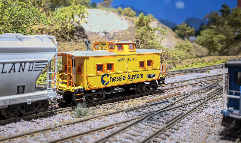 From
From 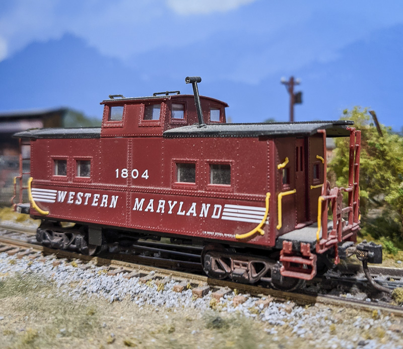 Starting with a Proto 2000 Steel Center Cupola Caboose I used the following material to complete this project.
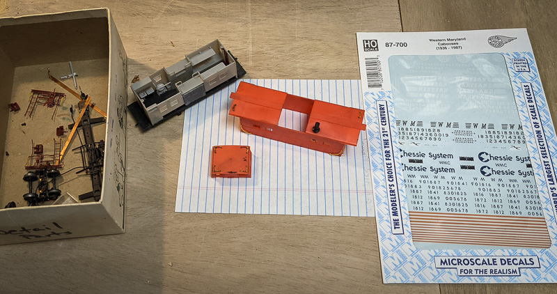 Disassemble and paint-strip the caboose. 90% isopropyl alcohol in a glass jar works very well to strip paint. Let it soak overnight. Scrub with a toothbrush and let it soak another evening. After round two the paint will be gone. Wash in hot soapy water, rinse well, and let dry. All the parts stay in a project box until needed.
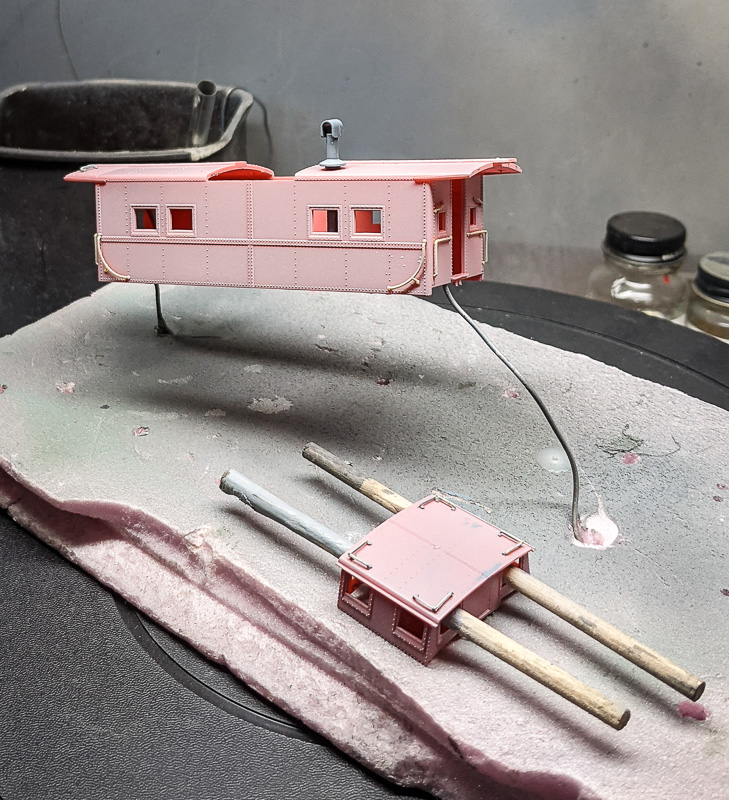 The first trip to the paint booth is for the primer. I use whatever gray I have on hand, shot through a Badger dual-action brush, and spray at about 15
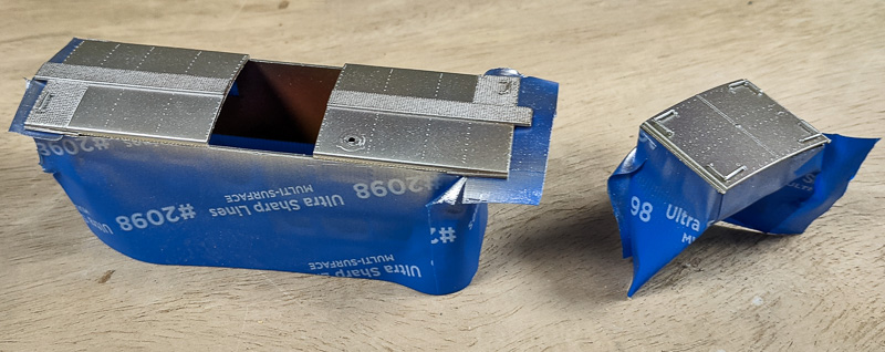 Next, mask the body and shoot the aluminum paint for the roof. 3M #2098 UltraSharp Lines Multi-Surface painters tape is my favorite masking tape. Rarely will there be paint bled-through and the edge of this tape is razor-sharp.
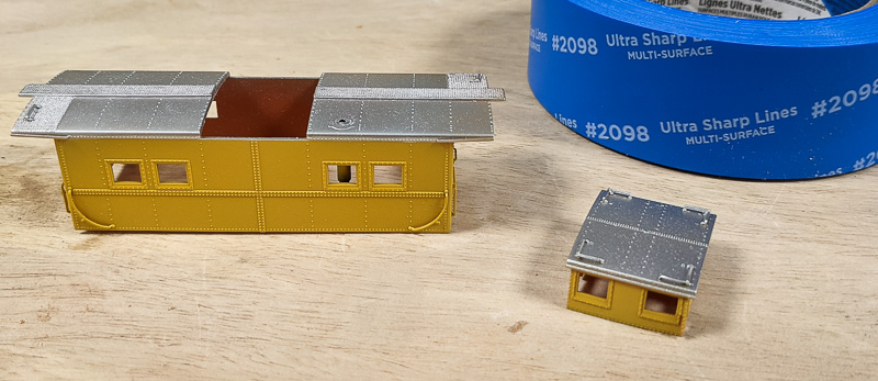 After the roof color has been applied, mask the roof and shoot the yellow next.
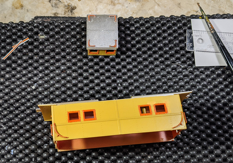 Now the tedious part comes into play, painting the window and door sashes. I use
 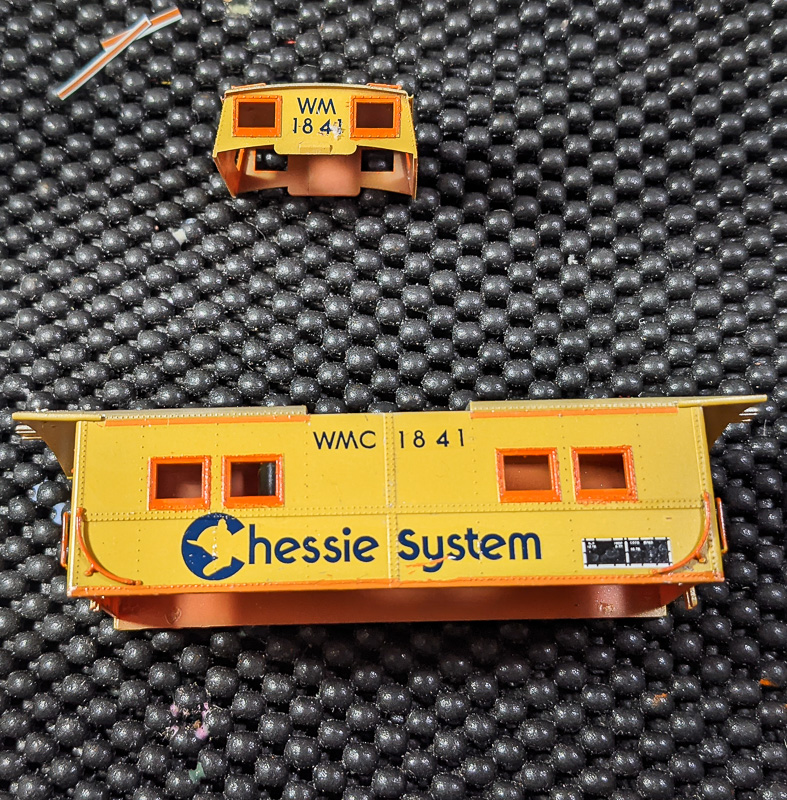 Another trip to the paint booth to shoot a gloss coat on the car,
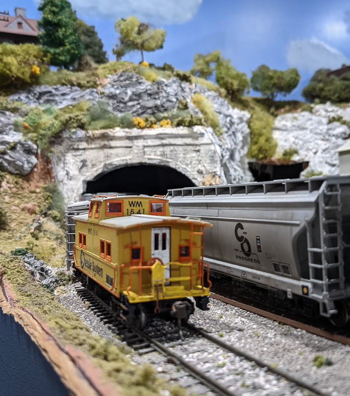 The end platforms were hand-painted using the
  The worst area (above) is that area previously known as Warren’s Gap. The inside track was 49” radius and the outside track 53” radius. So, I removed the track and roadbed and rebuilt that area with the inside track at 60” and the outside track at 64”.
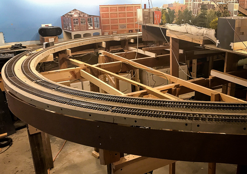 This will become New Freedom with a small town (above), a business or two, plus the PRR passenger station.
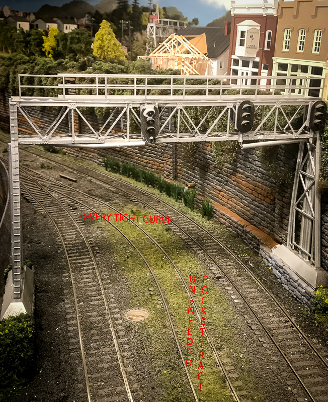 A second area (above) had a pocket track leftover from South Shore days and because of the switch and pocket track, there was an “S” curve of about 48” radius.
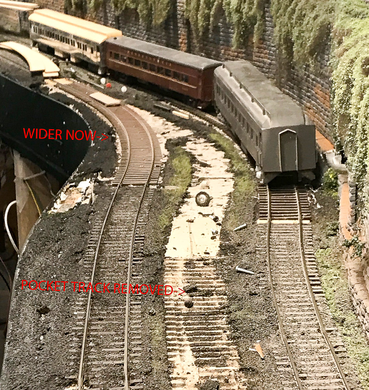 I removed the switch and the pocket track
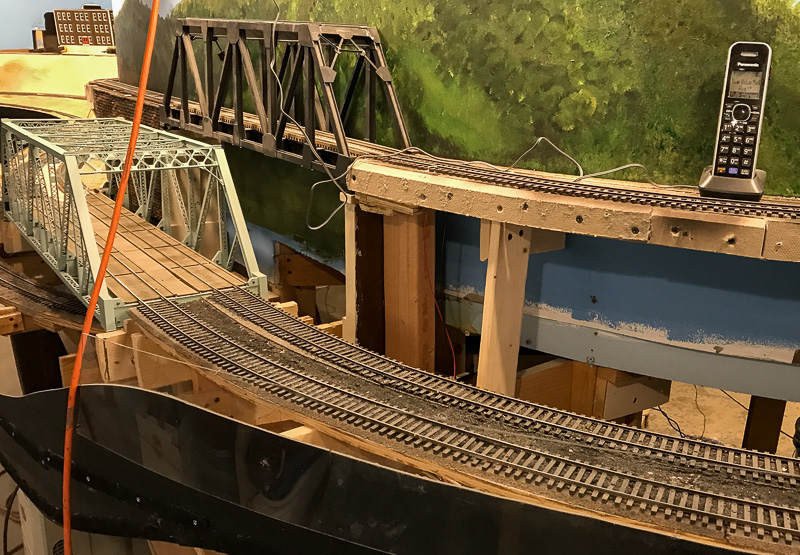 Another major area that requires widening (above) is the area entering Baltimore. It includes an Atlas double track truss bridge. The approaches to the bridge in both directions varied from 48” to 60”. I am still in the process of removing the old track and extending the benchwork (below) about 3-4 inches to allow for 60” and 64” standards.
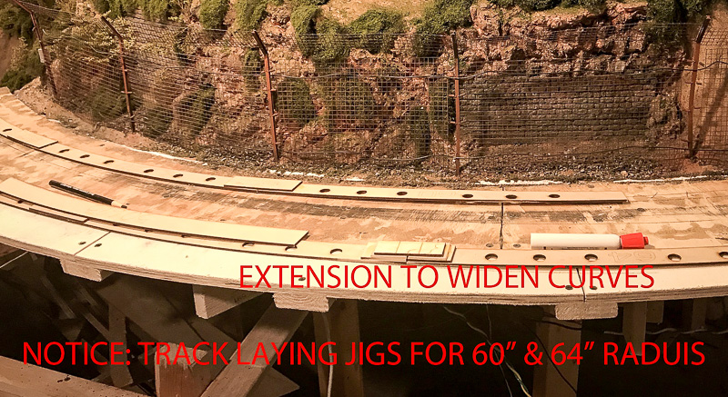
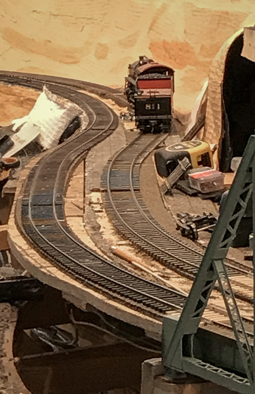 I am not sure if the bridge will still fit so the tracks at the end of the bridge (left) may need to be re-laid to 60” radius. The photo shows the tracks before being enclosed by a tunnel.
 From
From 