Mainline Hobby Supply Layout Tours, September 2023

Mainline Hobby Supply

Open House / Layout Tours

16 & 17 September 2023

Mainline Hobby reports they have will several new layouts to view and lots of changes to the familiar layouts.

To participate you must show up at the store, 15066 Buchanan Trl E, Blue Ridge Summit, PA, 17214 (doors open at 9:00 AM Saturday, 12:00 PM on Sunday). Ask for a tour book. There is no charge for this event.

Layout Tours 17 & 18 September

As part of the Mainline Hobby Supply 32nd annual Open House and Layout Tours, the following South Mountain Division  (SMD) members will open their layouts. Registration and layout tour guides must be obtained from Mainline Hobby Supply inc Blue Ridge Summit, PA on the weekend of the tours.

Dave Moltrup’s Beaver Falls & Shenango Railroad

This HO-scale Railroad is a freelanced steel mill set in the late 1960’s. Size is 19′ x 24′. Operation is by NCE, DCC system.

Jay Beckham’s Pennsylvania Railroad O-Scale Layout

Jay Beckham’s Model Railroad Layout. O Scale model of the Pennsylvania Railroad Northern Central branch from Penn Station Baltimore, MD to Harrisburg, PA. Trains will be running. Light refreshments will be served. This model railroad occupies our 1800 sq. ft. basement. Scenery is about 70% complete. Other photos at https://jaysoscalelayout.blogspot.com/ and on Jaysoscalelayout group on Facebook.

Don Florwick’s Pittsburgh & South Pennsylvania Railroad

This is a proto-freelanced HO layout based on the never finished route of the South Pennsylvania RR envisioned by the New York Central in the late 1800s. On Don’s 1955 version the NYC competes with the PRR across southern Pennsylvania connecting at Harrisburg PA with the Reading and at Pittsburgh with the NYC subsidiary P&LE. First generation lightning-stripe painted NYC diesels have just replaced steam to power passenger and freight traffic on this busy single-track TT&TO operated mainline.

Steve King’s Virginia Midland

The Virginia Midland is a fully operational N-scale railroad located in the Virginia and West Virginia area and set during the 1969 period.  The layout is about 10 scale miles long and operates between two staging areas representing Marion, Virginia and Welch, West Virginia.  One passenger train, four freight trains, plenty of coal trains, and several daily mine runs keep the layout busy.

Bob Johnson’s West Virginia Midland

The West Virginia Midland is a HO scale freelance short line (based on a combination of several prototypes) which runs between the B&O at Holly Junction, WV and the Western Maryland at Laurel Bank, WV. Both the B&O and the WM have industry specific haulage rights on the Midland. The time period is summer 1954.

Major traffic producers on the Midland include a limestone quarry, coal mine (with a second simulated in staging) coke ovens, lumber mill (pending construction) with associated logging traffic and an industrial area around the Webster Springs / Cherry Falls area.

Scenery is approximately 90% completed

With the exception of two gas mechanical industrial switchers the WVM is 100% steam with a large number of geared locomotives (B&O and WM interchange power is diesel)

Operation is by TT&TO

The layout has an E-shaped 12 ft. by 16 ft. main area with a 50 ft. “around the wall” shelf extension.

The layout is designed so that each major industry is a “stand alone” scene that is large enough to be a viable source of revenue for the railroad. The intervening areas are modeled as open country to preserve the feeling of a rural short line railroad.The design of the railroad puts a heavy emphasis on local trains with extensive switching requirements.

Bob Morningstar’s Western Maryland Railway – Hagerstown Subdivision

This is my recreation of my childhood and teenage years of railfanning in and around the Hagerstown area. The layout represent the Western Maryland Railway, circa 1978-1983, more or less. It covers the Hagerstown terminal area, NC tower, and points west to Hancock.The layout encompasses a dedicated layout room of 14’ x 16’.   Cement operations in and around Hagerstown play a large role in the operations. There is a large cement plant in Pinesburg, MD that requires daily servicing. In addition, there is a cement hopper clean out facility in Hagerstown that supports cement operations.  Numerous industries are serviced by locals that originate out of Hagerstown. The B&O Weverton branch (severed by Hurricane Agnes in 1972) is now serviced out of Hagerstown. There are numerous industries to be serviced east of Hagerstown via the Security Branch of the B&O.

Transfer runs to and from the Conrail and N&W connection at Vardo Yard are important sources of interchange traffic.

Disguising Atlas Switch Machines

From John Pursell

I use Atlas switch machines on my layout. They’re reasonably priced, reliable, and available just about everywhere. I’ve even gotten used to the “buzz-clack” sound as one of them operates. What I’ve never gotten used to, though, is the big, honkin’ piece of black plastic that houses the solenoid. It lays right by the track and, in my opinion, bears no resemblance to anything prototypical. Because of this, I’ve devised ways to hide or disguise them.

I am aware of Atlas’s switch machines for “under table” mounting. I’ve used them in the past and they work well. But as my age advances and bad knees become more of a fact of life, I want to make as few trips as possible under my layout. I’ve decided to keep switch machines above ground, so to speak. I also know that Atlas includes a little piece of black plastic that allows you to mount the machine a bit further away, but even that’s not far enough for me. I prefer to have at least 3 to 4 inches between a turnout and the machine to allow for my coverings.

The first thing I do is work out a way to mount the machine at least a few inches away from the turnout and create the connection. When mounting them in this way, Atlas’s “left/right hand” switch machine designations do not matter because those cast-on track connections won’t be used.

My method uses a piece of green florist wire that is about 3/4 inch longer than the distance between the center of the turnout’s points and my Atlas switch machine throw bar’s location. First I measure 3/8 inch from one end of the wire and bend it up 90 degrees. Then I measure 1/8 inch from the tip on that bent end and bend it another 90 degrees, perpendicular to the first bend. Fit it into the hole on the turnout’s throw-bar. It should now extend, perpendicular to the track section, underneath the throw-bar. I do this before I mount the turnout on the roadbed.

Trim the roadbed under the throw-bar to allow the wire to freely move under the points. Note that the wire must also lay flat on top of the throw-bar so a passing coupler trip pin doesn’t get snagged.

It may take some trial and error to get this right. I use code 100 track and the measurements for bending could be different for different codes of rail or other manufacturer’s track. The measurements above are estimated. Florist wire is inexpensive. If it’s not correct, I toss it and do another.

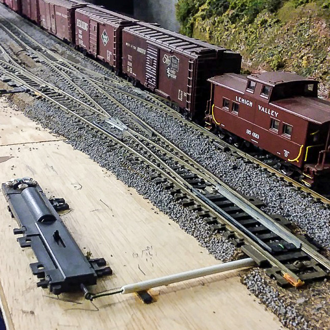
Next, with the wire protruding out from the turnout to where the machine mounting spot will be I run the wire through a length of plastic tube that will fit between the roadbed and the machine. This allows me to cover the connection, preventing scenic material and adhesives form interfering with its movement. At the switch machine, the wire is bent around the actuating lever and squeezed down using pliers to reduce any play.

Holding the switch machine in it’s mounting spot, I check to see if everything works. In general, I keep the switch machine and turnout parallel to one another. When it functions smoothly, I permanently attach the switch machine and turnout with adhesive caulk. This will hold it, more or less, permanently. Since caulk always retains some resiliency, I’ll be able to replace it (with perhaps some small effort) if necessary. On occasion, I’ve mounted the machine on a small piece of cork roadbed, which puts it at the same height as the turnout. Using this method allows me to run a longer actuating (floral) wire under an adjacent track inside the plastic tube.

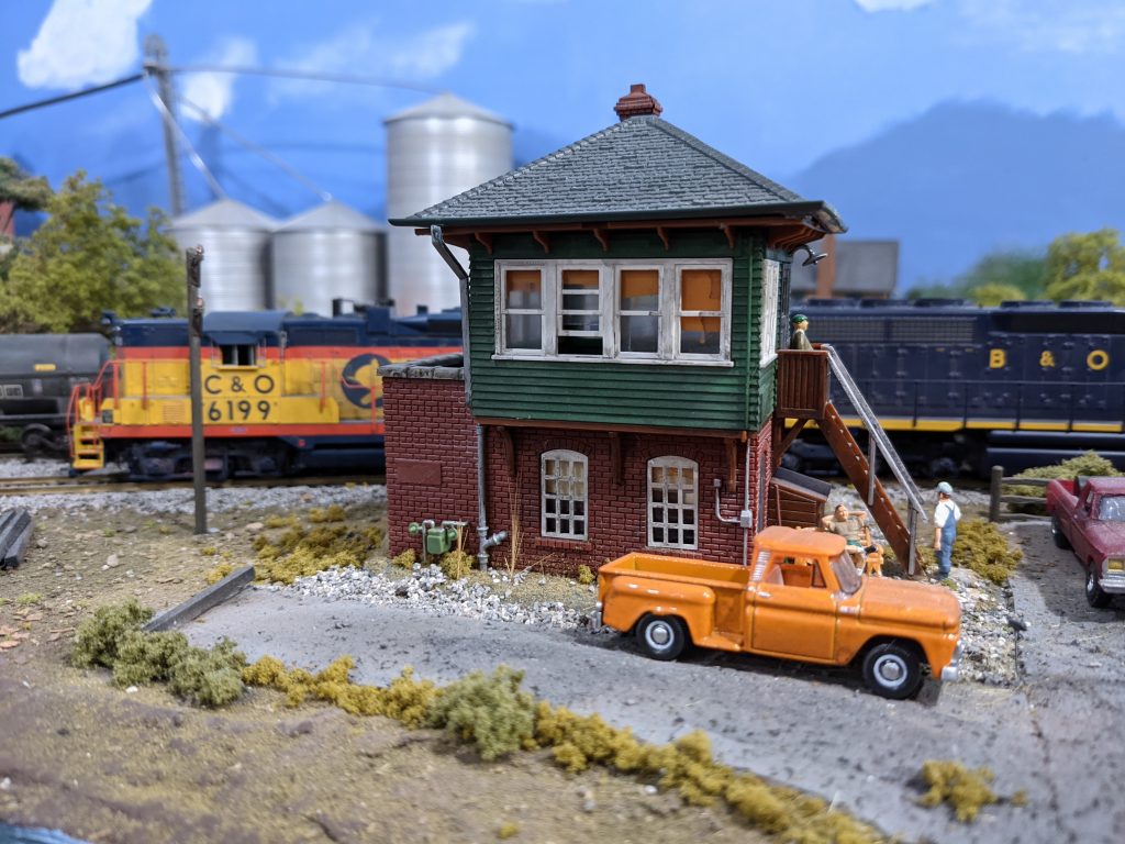
Disguising the machine consists of multiple methods. All of this should work for other types of switch machines. One advantage of Atlas machines is they are fairly flat. This helps with hiding them. The accompanying photo shows several of the ways I’ve done this. A small building with a slot for the wire to go through can be whipped up in minutes. Leave the building loose for adjustments or repairs. I also hide them behind trees or ground foam bushes. If going this route, I cover the actuator pin opening in the machine while gluing, painting, or working with foam. I’ve can also made a small knoll out of carved foam to fit over the machine, covering the knoll with ground foam, grass, and weeds to blend in the rest of the scenery. If this knoll is by an industrial area, I would cover it with mixed, small pieces of junk to resemble a scrap pile. Since the machines are flat, I’ve also hidden them behind fences, extend an inch or two beyond the edges of the machine, completely hiding them. Fences are often good if there’s just no room for anything else.

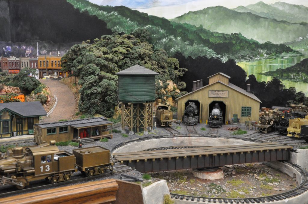
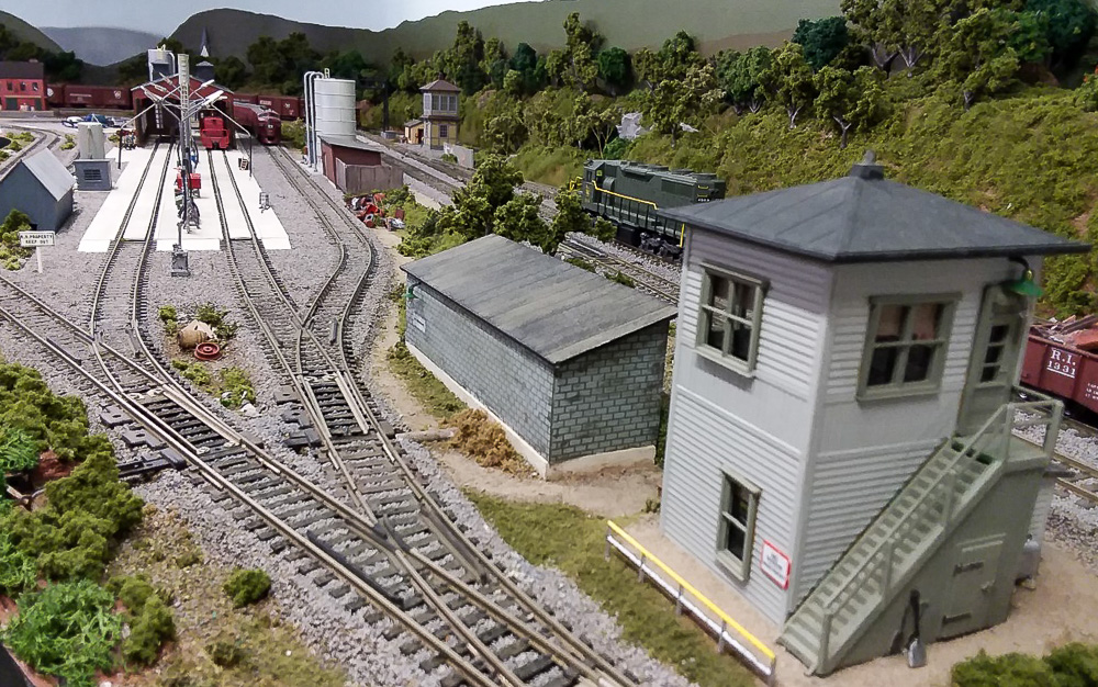
Above is the Easton engine terminal on my Lehigh Valley RR, where six Atlas switch machines are hidden. Clockwise from the left: #1 inside the gray shed, #2 inside the red shed, #3 behind the hillside, #4 behind the bushes, #5 behind the block shed and #6 behind the shrubs across from the block building.

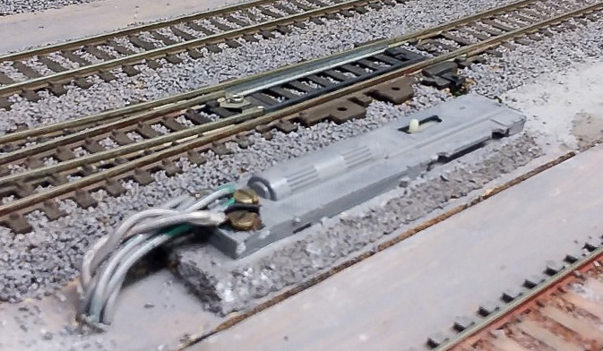
However, there are “worst case” scenarios. What if there’s simply no space for mounting the switch machine other than right by the track as Atlas intended? If I can’t hide it, I camouflage it. This is easily done by painting the machine (below) the same color as the ballast, making it much less noticeable. Oddly enough, over the years I’ve met many modelers who have simply never thought that you could paint the switch machine. As long as paint doesn’t get into the operating area it works fine. Depending on the surrounding scenery, I recommend gluing a few small pieces of foam on the sides to help the machine blend in better.

So that’s how I do it. It’s not difficult and allows me to keep using my preferred brand of switch machine. Try it and see if you like it. I assure you, your back and your knees will thank you!

EBT Post Office Pushcart

From Pete Clarke

It’s quiet right now in Robertsdale, PA. But the mail train will soon arrive. So the post office clerk has positioned the pushcart into the spot where the crew will offload mail from the combine. The clerk will then push the cart over to the Post Office building, and toss the mail through the window. Every time he does this  chore I’m sure he asks himself, “why could  they bother to lay this track, but not bother to put in a door!”

That’s the way it was on the EBT. That’s the way it is on Pete and Jane Clarke’s HOn3 EBT as well.

  • Thank you to Wade Woodcock for the 3-D printed “Old Post Office” kit. Frank Benenati assembled the structure.

NMRA Recommended Practices

Real Men Don’t Read NMRA’s Recommended Practices

From Jay Beckham

In 2000 I changed from HO to O scale. In HO a 36-inch minimum radius was a nice-looking curve. I  figured that 50-inch would be fine for O scale, particularly since I was modeling the South Shore which was an interurban line. I also did not consider that if I found a Little Joe it would require a larger radius because of its two eight-wheel trucks. But real men don’t read NMRA’s Recommended Practices (RP).

Now, jump forward 20 years to modeling the PRR’s Northern Central branch from Baltimore to Harrisburg, and the recent purchase of two PRR EMD E8 units. These engines have all-wheel pick-ups and are close-coupled. They run poorly on my curves. Then I added some 80-foot passenger cars, and the derailing began. My disregard for radius had come back to bite me.

According to the NMRA Recommended Practices, six-wheel trucks and 80-foot cars require a 58-inch minimum radius. Due to existing constraints, I am compromising with a 60-inch minimum. The RP also recommends a #6 switch. I have dozens of Atlas #5s. Fortunately, when I built the Penn Station area, I had laid large radius curves. I did the same at the site of my northbound staging representing the New York area.

The worst area (above) is that area previously known as Warren’s Gap. The inside track was 49” radius and the outside track 53” radius. So, I removed the track and roadbed and rebuilt that area with the inside track at 60” and the outside track at 64”.

This will become New Freedom with a small town (above), a business or two, plus the PRR passenger station.

A second area (above) had a pocket track leftover from South Shore days and because of the switch and pocket track, there was an “S” curve of about 48” radius.

I removed the switch and the pocket track  (above) to eliminate that problem.

Another major area that requires widening (above) is the area entering Baltimore. It includes an Atlas double track truss bridge. The approaches to the bridge in both directions varied from 48” to 60”. I am still in the process of removing the old track and extending the benchwork (below) about 3-4 inches to allow for 60” and 64” standards.

I am not sure if the bridge will still fit so the tracks at the end of the bridge (left) may need to be re-laid to 60” radius. The photo shows the tracks before being enclosed by a tunnel.

There are many more areas on the layout that may require radius corrections. They will be addressed in the coming months. I plan to build #6 switches using Fast Tracks and replace all my Atlas #5 switches. The nickel-silver plating is wearing off most of those switches anyway, and a #5 is below the recommended practices. In addition, the frogs are very difficult to solder leads to for powering.

So, what have I learned in this process? Standards and recommended practices have a purpose. My advice is to do your homework. Pay attention to what others say and have experienced. You may be able to apply their methods to your work.

After building a large layout I feel I could write a book about things to do and not to do.

Consider layout height so you can sit underneath to work on switches and wiring. Consider sectional construction so you can move without destroying years of work. Keep detailed spreadsheets of everything on the layout for the sake of your heirs. I feel I could go on and on.

Photos by Jay Beckham and Wilbur Snyder