Achievement Program Certificates Awarded

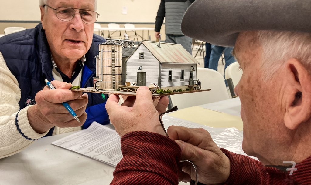
Bob Charles (left) and Bob Johnson review structures made by John Pursell after the annual Mini Con in April 2024. The dioramas are entries for the Achievement Program structure certificate. (Tom Fedor)

NMRA Achievement Program (AP) certificates awarded to John Purcell.

Kurt Thompson, MMR and MER AP Manager reported in The Local that John has added Model Railroad Author and Master Builder – Structures to his list of certifications.

You can read more of John’s writing and see more of his modeling in past editions (years 2021/22 and later) of your Wheel Report <https://portal.smdnmra.org/497-2/>.

KATO DCC Project

Modeling Tips & Lessons Learned

By Frank Benenati

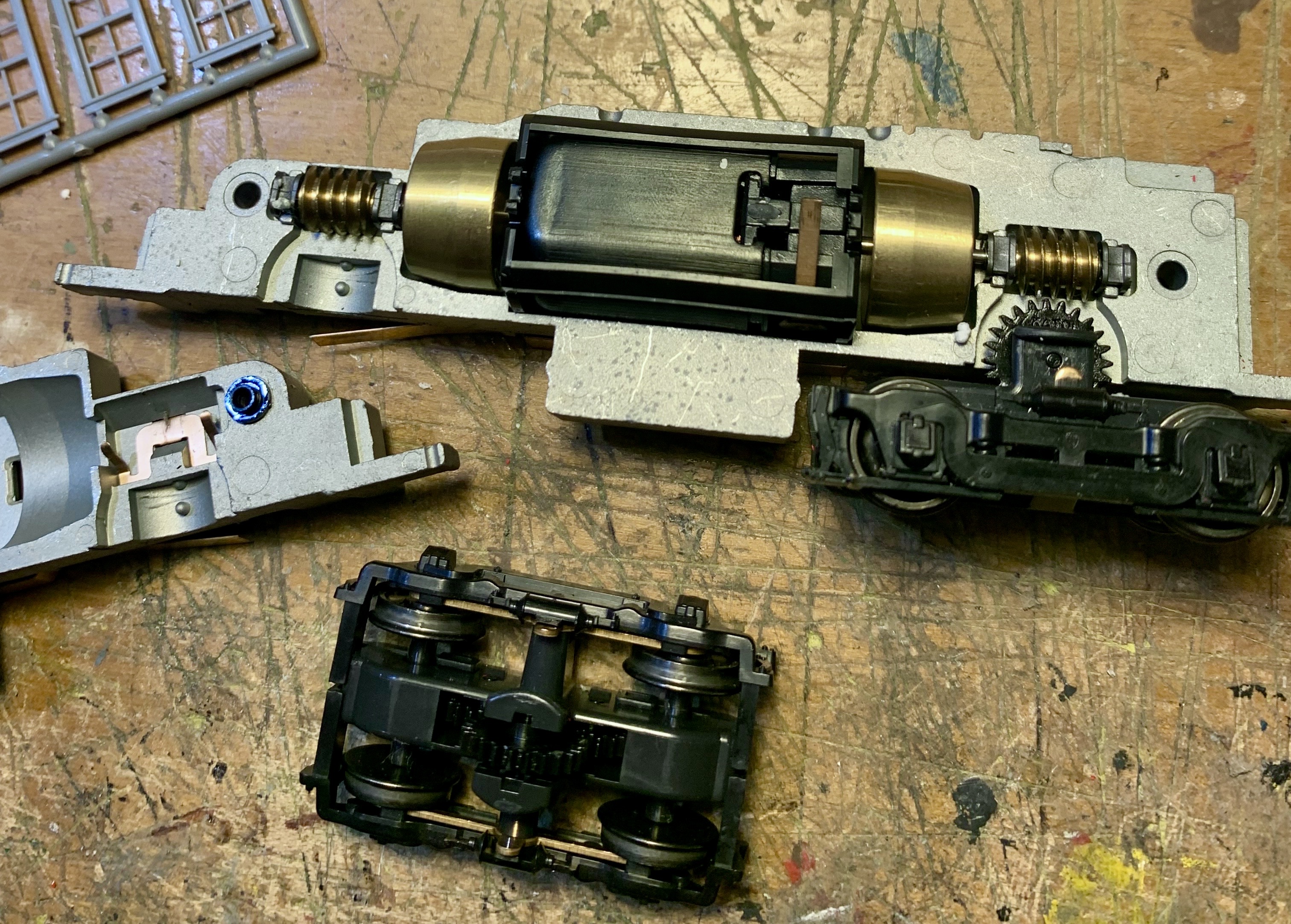
 A friend needed help installing a DCC decoder and keep alive in an HO scale Kato EMD NW2 switcher they plan to repaint. Given the cost of a TCS (Train Control Systems) M1 small form factor decoder, a TCS KeepAlive, and taking into account the Kato design, shown below, a new or used switcher with factory installed DCC, sound, and keep-alive might have been a better option. The split metal frame would require time consuming milling to fit even the smallest of decoders, plus electrical isolation of the motor from the shell.

We were about to “scrap the project” until I discovered a Lenz Digital Plus Silver decoder in my electronic parts bin. It had previously been installed in an HOn3 steam locomotive and later in an HO Alco RS3. Most importantly, the decoder added no out-of-pocket cost to the project. The downside, it was larger than the TCS M1 and therefore require a larger pocket (more cutting, grinding, and filing). Several wire leads also needed to be replaced and soldered onto the decoder board. 

Before I plugged in my Dremel and changed the blade in my hacksaw, I thought it best to test the recycled decoder and my soldering skills.

 Modeling Tip

 To test, I attached the decoder red and black wires to a Sprog II and the orange and grey wires to a test track. After placing the NW2 on the test track, I used DecoderPro to reprogram the decoder and check the Kato for gear noise, running smoothness, and switching potential. End result, the Kato design lived up to it’s reputation and ran extremely well. We decided to install the Lenz decoder and forego adding a keep alive.

Cutting the decoder pocket, below, in the top of the shell was time consuming. 

 Installation was a success. A smooth running switcher, limited conversion cost, and a happy friend.

Lesson Learned

While I most likely would not volunteer to do another Kato NW2 conversion, I am looking forward to a crab cake lunch and running this rebuilt NW2 on their model railroad.


If you decide to take on a Kato NW2 conversion, TCS provides detailed instructions for installing their M1 decoder here:<https://drupal.tcsdcc.com/installation/ho-scale/1358>.

Disguising Atlas Switch Machines

From John Pursell

I use Atlas switch machines on my layout. They’re reasonably priced, reliable, and available just about everywhere. I’ve even gotten used to the “buzz-clack” sound as one of them operates. What I’ve never gotten used to, though, is the big, honkin’ piece of black plastic that houses the solenoid. It lays right by the track and, in my opinion, bears no resemblance to anything prototypical. Because of this, I’ve devised ways to hide or disguise them.

I am aware of Atlas’s switch machines for “under table” mounting. I’ve used them in the past and they work well. But as my age advances and bad knees become more of a fact of life, I want to make as few trips as possible under my layout. I’ve decided to keep switch machines above ground, so to speak. I also know that Atlas includes a little piece of black plastic that allows you to mount the machine a bit further away, but even that’s not far enough for me. I prefer to have at least 3 to 4 inches between a turnout and the machine to allow for my coverings.

The first thing I do is work out a way to mount the machine at least a few inches away from the turnout and create the connection. When mounting them in this way, Atlas’s “left/right hand” switch machine designations do not matter because those cast-on track connections won’t be used.

My method uses a piece of green florist wire that is about 3/4 inch longer than the distance between the center of the turnout’s points and my Atlas switch machine throw bar’s location. First I measure 3/8 inch from one end of the wire and bend it up 90 degrees. Then I measure 1/8 inch from the tip on that bent end and bend it another 90 degrees, perpendicular to the first bend. Fit it into the hole on the turnout’s throw-bar. It should now extend, perpendicular to the track section, underneath the throw-bar. I do this before I mount the turnout on the roadbed.

Trim the roadbed under the throw-bar to allow the wire to freely move under the points. Note that the wire must also lay flat on top of the throw-bar so a passing coupler trip pin doesn’t get snagged.

It may take some trial and error to get this right. I use code 100 track and the measurements for bending could be different for different codes of rail or other manufacturer’s track. The measurements above are estimated. Florist wire is inexpensive. If it’s not correct, I toss it and do another.

Next, with the wire protruding out from the turnout to where the machine mounting spot will be I run the wire through a length of plastic tube that will fit between the roadbed and the machine. This allows me to cover the connection, preventing scenic material and adhesives form interfering with its movement. At the switch machine, the wire is bent around the actuating lever and squeezed down using pliers to reduce any play.

Holding the switch machine in it’s mounting spot, I check to see if everything works. In general, I keep the switch machine and turnout parallel to one another. When it functions smoothly, I permanently attach the switch machine and turnout with adhesive caulk. This will hold it, more or less, permanently. Since caulk always retains some resiliency, I’ll be able to replace it (with perhaps some small effort) if necessary. On occasion, I’ve mounted the machine on a small piece of cork roadbed, which puts it at the same height as the turnout. Using this method allows me to run a longer actuating (floral) wire under an adjacent track inside the plastic tube.
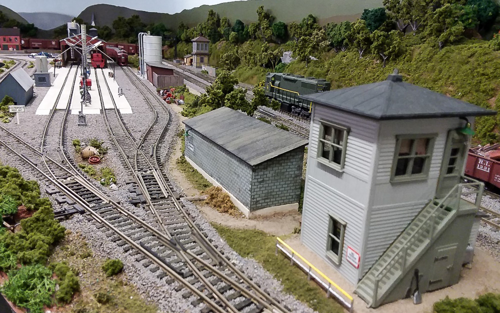
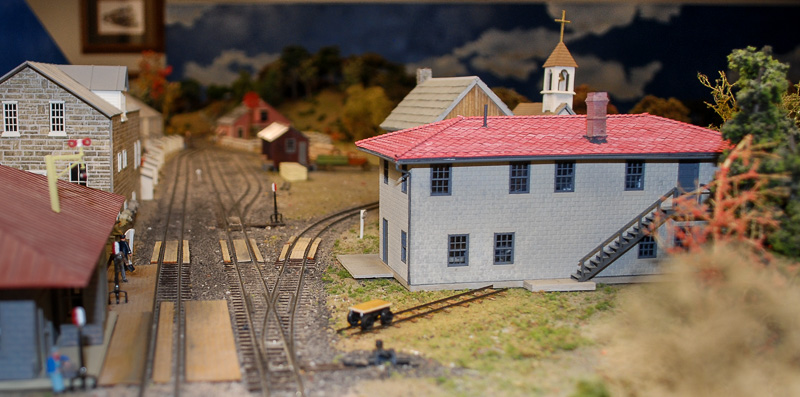
Disguising the machine consists of multiple methods. All of this should work for other types of switch machines. One advantage of Atlas machines is they are fairly flat. This helps with hiding them. The accompanying photo shows several of the ways I’ve done this. A small building with a slot for the wire to go through can be whipped up in minutes. Leave the building loose for adjustments or repairs. I also hide them behind trees or ground foam bushes. If going this route, I cover the actuator pin opening in the machine while gluing, painting, or working with foam. I’ve can also made a small knoll out of carved foam to fit over the machine, covering the knoll with ground foam, grass, and weeds to blend in the rest of the scenery. If this knoll is by an industrial area, I would cover it with mixed, small pieces of junk to resemble a scrap pile. Since the machines are flat, I’ve also hidden them behind fences, extend an inch or two beyond the edges of the machine, completely hiding them. Fences are often good if there’s just no room for anything else.

Above is the Easton engine terminal on my Lehigh Valley RR, where six Atlas switch machines are hidden. Clockwise from the left: #1 inside the gray shed, #2 inside the red shed, #3 behind the hillside, #4 behind the bushes, #5 behind the block shed and #6 behind the shrubs across from the block building.

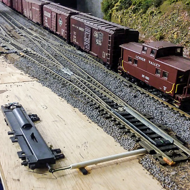
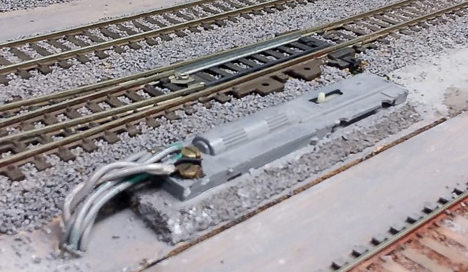
However, there are “worst case” scenarios. What if there’s simply no space for mounting the switch machine other than right by the track as Atlas intended? If I can’t hide it, I camouflage it. This is easily done by painting the machine (below) the same color as the ballast, making it much less noticeable. Oddly enough, over the years I’ve met many modelers who have simply never thought that you could paint the switch machine. As long as paint doesn’t get into the operating area it works fine. Depending on the surrounding scenery, I recommend gluing a few small pieces of foam on the sides to help the machine blend in better.
So that’s how I do it. It’s not difficult and allows me to keep using my preferred brand of switch machine. Try it and see if you like it. I assure you, your back and your knees will thank you!

EBT Post Office Pushcart

From Pete Clarke

It’s quiet right now in Robertsdale, PA. But the mail train will soon arrive. So the post office clerk has positioned the pushcart into the spot where the crew will offload mail from the combine. The clerk will then push the cart over to the Post Office building, and toss the mail through the window. Every time he does this  chore I’m sure he asks himself, “why could  they bother to lay this track, but not bother to put in a door!”

That’s the way it was on the EBT. That’s the way it is on Pete and Jane Clarke’s HOn3 EBT as well.

  • Thank you to Wade Woodcock for the 3-D printed “Old Post Office” kit. Frank Benenati assembled the structure.

WM Caboose Repaint

From Bob Morningstar

I model the waning years of the Western Maryland (WM) when the Chessie System colors were rapidly erasing any visages of the WM from the rails. The Western Maryland had 105 “Northeastern” style cabooses on the roster. A complete WM caboose roster is located at alphabetroute.com/wm/rosterpdfs/WMCabooseClass.pdf.

Lifelike produced a huge number of these caboose years ago. They are readily found at train shows and on eBay. I acquired a few of these in both the boxcar red “Speed Lettering” and “Circus Color” paint schemes, and need to bring the “Speed Lettering” cars forward, era-wise, into the 1980s.

Starting with a Proto 2000 Steel Center Cupola Caboose I used the following material to complete this project.

  • MicroScale Industries 87-700 Western Maryland Cabooses decals
  • Tru-Color TCP-33 Aluminum paint
  • Tru-Color TCP-305  Chessie Yellow
  • Badger ModelFlex – UP Harbor Mist gray – used as a primer, use whatever primer you like best

Note: For the Vermilion sash and door trim you could use Tru-Color TCP-307 Chessie Red-Orange. I used a bottle of the actual Chessie Vermilion that was given to me decades ago by a WM shop foreman. I have carefully kept it sealed all these years and it was still usable after being thinned for the brushwork.

Note: Tru-Color paints require acetone cleanup. You may want to substitute your favorite water-based acrylic-based paints as I find that Tru-Color is difficult to airbrush and cleanup.

Disassemble and paint-strip the caboose. 90% isopropyl alcohol in a glass jar works very well to strip paint. Let it soak overnight. Scrub with a toothbrush and let it soak another evening. After round two the paint will be gone. Wash in hot soapy water, rinse well, and let dry. All the parts stay in a project box until needed.

The first trip to the paint booth is for the primer. I use whatever gray I have on hand, shot through a Badger dual-action brush, and spray at about 15  psi.

Next, mask the body and shoot the aluminum paint for the roof. 3M #2098 UltraSharp Lines Multi-Surface painters tape is my favorite masking tape. Rarely will there be paint bled-through and the edge of this tape is razor-sharp.


After the roof color has been applied, mask the roof and shoot the yellow next.


Now the tedious part comes into play, painting the window and door sashes. I use MicroScale Industries Micro Mask and a 2/0 or 0-size brush to carefully apply the Micro Mask to the body around the window sash.  This is in lieu of using the 3M tape which is very time-consuming to cut and apply.

Using a 2/0 brush apply the vermilion color to the sashes and door frames. The key to a professional-looking finish is being comfortable while applying both the Micro Mask and vermilion paint. I work at a well-lit workbench, use an Opti-Visor with LED lighting, and a foam-based car cradle to hold my work.   I also rest my painting arm and elbow on a soft towel so that I don’t become uncomfortable and rush the work.

Another trip to the paint booth to shoot a gloss coat on the car,  I use MicroScale Micro Gloss and thin it slightly before airbrushing. I have also had success using Pledge Liquid Floor Gloss. Thin it with water and brush it on the areas where you will be applying decals.

I consider the best book written on WM cabooses to be “Western Maryland Cabooses” by Dwight Jones. Another valuable photographic resource for these cabooses from the Chessie era can be found at hebners.net/Caboose/bowm.html.

Using a prototype photo, cut the decal sheets to obtain what you need. I cut the decals as close to the artwork as possible using either a hobby knife with a fresh blade or manicure scissors. Apply the decals after letting them soak just long enough to slide off the backing paper. Position in place and let dry. After the decals are fixed in place apply your favorite decal setting solution, in my case that is slightly thinned Walthers SolvaSet. This wetting/softening solution is very aggressive and older decals may start dissolving or falling apart if you use it without thinning.

I model the early 1980’s so a Clean, Oil, Test, and Stencil (COTS) decal was applied. Notice there is no ACI label. The railroad industry gave up on the ACI car identification system in the late 1970s due to the unreliability of reading the labels and the cost involved in maintaining them.

The end platforms were hand-painted using the Tru-Color Chessie Yellow and the end rails were done in my vermilion color.

Again, images of the ends of the car are very useful as there seems to be a wide variation as to what safety appliances (handrails, step tread edges, and grab irons) got the vermilion color depending on who did the repaint.

One last trip to the paint booth for a shot of clear flat to hide the decal edges,  I use Badger ModelFlex 16-601 Clear Flat or if I want to go “old school” I’ll shoot Floquil Flat Finish. 

Finishing up the model included painting the wheel faces and backs with a muddy/grime color, I use a cheap acrylic paint from Hobby Lobby made by FolkArt called #940 “Coffee Bean”. It has just the right amount of brown and dark tints that makes for a convincing wheel finish. The Kadee couplers are lightly painted with the same color using care not to gum up the workings of the knuckle.

Weathering involves using light gray, black, and brown powders that I get by shaving art pastels. I shave the individual colors into an egg container compartment. This technique has worked very well and is inexpensive compared to buying weathering powders sold for model railroad applications.

After weathering, the car is complete and ready to get back on the rails. It takes me about 4 hours in total to do one of these way cars, spread over a week of evenings. I hope you enjoyed this how-to feature and picked up an idea or two.