

Thank you to those who contacted me about their aspirations in the Achievement Program (AP). I look forward to presenting your awards! Several of you are ready to have your scenery judged. This takes some coordination to get (preferably) three judges together. I appreciate your patience.
To qualify for the Model Railroad Engineer–Electrical certificate, you must:
A. Construct and demonstrate on your own or club layout, the satisfactory operation of an electrical control system on a model railroad capable of simultaneous and independent control of two mainline trains in both directions, and containing at least:
- Simultaneous and independent control of two mainline trains. This can be as simple as a single track main with sidings. This means that as long as you can cut power to the sidings individually, you can run one train, park it on a siding while you run another, then park it and run the first again. This meets the requirement.
- For conventional DC wiring (non-command-control), five electrical blocks that can be controlled independently. For command control wiring (DCC, TMCC, and others), sufficient gaps and switches to maintain polarity, phase if needed, and troubleshooting.
- One mainline passing siding.
- One reversing loop, wye, turntable, or transfer table.
- One yard with a minimum of three tracks and a switching lead independent of the main line. (“Independent” means that you are able to operate the locomotive switching the yard and the lead on a separate powerpack without interfering with mainline operations.)
- Facilities for the storing of at least two unused motive power units. Don’t make this harder than it is – these are just sections of track (usually spurs) that you can cut power to independent of the main.
- One power supply with protective devices (short indicator or circuit breaker) to ensure safe operation. You don’t have to build this yourself; you just have to have one in your control system. You can use a commercial supply that has these features, modify a commercial supply to add these features, or even build it yourself – but only if you REALLY know what you’re doing.
B. Wire and demonstrate the electrical operation of at least three of the following items:
- Turnout. Wiring up the simplest powered turnout from your hobby store will satisfy this requirement.
- Crossing. Most commercial crossings come pre-wired. Just set one up so that you can run trains through on both tracks.
- Crossover
- Double Crossover
- Slip Switch (single or double)
- Gauge Separation Turnout
- Double Junction Turnout
- Three Way Turnout
- Gauntlet Turnout
- Spring Switch
- Operating Switch in Overhead Wire
Note: Don’t make the requirements in parts B or C any harder than they have to be. You do not have to scratchbuild any of these; you just have to show that you can make them work electrically. Of course, if you want to go to the effort of building them yourself, you may learn many new skills in the process! The whole point of these requirements is for you to demonstrate a variety of skills.
C. Wire and demonstrate the electrical operation of at least three of the following items:
- Electrical turnout position indication on a control panel or at trackside for a minimum of four turnouts. (Remember that many commercial switch machines have electrical terminals to allow you to do this easily.)
- Track occupancy indication on a control panel or at trackside for a minimum of five blocks.
- Cab control, making provision for the connection of at least two power supplies to a minimum of five blocks as the trains progress. (This means that your layout has at least five blocks, each of which can be controlled by one of two power supplies. The five blocks DO NOT have to be in a row along the same stretch of track.)
- Engine terminal, including an electrically powered turntable or transfer table, a minimum of three stall tracks, and at least two blocked storage sections for parking locomotives outside the stall area. (This means you need to have a total of five tracks (three inside an engine house or roundhouse, and two outside), that you can cut power independently to store motive power).
- Two turnout junctions with electrical interlocking and protecting trackside signals. (This is simply a turnout with electrical protection to prevent a train from going through a turnout that is set against it. Again, the electrical terminals on a switch machine, combined with a couple of insulated rail joiners, make this a fairly easy project.)
- High Frequency Lighting (This is an old term for Constant Lighting.)
- Electronic throttle with inertia and braking provisions. (This requirement could be combined with requirement A-6, above.)
- Grade crossing with electrically actuated warning indication. (You don’t have to design or build the circuitry for this yourself. There are a number of commercial components available that you can just wire up to meet this requirement. Or you can use commercial plans that appear in magazines from time to time. Or you can do it from scratch.)
- Two-way block signaling with automatic train detection for at least five blocks. (See remarks under #8).
- Operating overhead wire, using either pantographs, trolley poles, or both for current collection. (Any traction fans out there?)
- Installation of an advanced electronic and/or computer control for the model railroad.
- Design, installation, and operation of animated mechanical and/or electrical displays. This doesn’t have to be a huge animated display – think about small eye-catching displays like animated industries or signs. Put a carousel in the local park or chase lights on the marque at the Bijou.
- Design, installation, and operation of mechanical and/or electrical layout lighting displays. (This means lights which illuminate the layout, as opposed to lighted things on the layout. For example, lighting which simulates the change from day to dusk to night)
- Installation of a command control receiver. Modifications or additions to the device’s wiring are required. Installing a plug-equipped decoder into a manufactured prewired socket is not sufficient.
- Installation of a command control throttle buss line around a layout capable of handling at least two throttles at three or more separate locations.
Commercially assembled complete units are not acceptable in the items below:
- Construction and installation of a sound system. This does not have to be an on-board sound system; it could be an under-the-layout system.
- Construction and installation of a signaling system.
- Development and installation of a CTC system.
- Installation and operation of an on-board video system.
- Computer generated block detection information.
- Hardwired or stored control program (i.e. computer) for operation of the railroad.
- Development and demonstration of a computer-to-railroad interface.
- Other. (Examples of ‘other’ includes flashing warning lights on locomotives, or end-of-train devices on cabooses, etc.)
Please note that operating third rail (center or outside) or overhead wire powered layouts may be considered for ALL aspects of the AP. Also note that the use of advanced power supplies, train control, track wiring, and track control methods shall not be restricted by the definitions in the minimum requirements listed above.
These items may not appear to be equal in difficulty – they aren’t meant to be. They are meant to provide a wide variety of things that people may have done that they can get credit for.
D. Prepare a schematic drawing of the propulsion circuitry of the model railroad in part (A) showing the gaps, blocks, feeders, speed and direction control, electrical switches, and power supplies.
Note that this requirement includes ONLY the propulsion circuitry. It is not required to include the wiring for electrical turnout control, signal systems, building lighting, etc. You do not need to include the details for parts of the diagram which are repeated. If a number of parts are wired in the same way, it sufficient to draw one section in detail and indicate other locations with rectangles.
E. Prepare schematic drawings identifying the wiring and components of the six items under parts (B) and (C).
For the sake of clarity, these schematics should probably be separate from the propulsion circuitry schematic in part (D), above. If you already have one over-all schematic of the layout, you might want to consider making multiple copies and going over the applicable lines with a highlighter for each feature.
Note that this is just turning in the kind of documentation that you should be preparing for your layout anyway. It will make trouble shooting much easier in a couple of years when you’ve forgotten how it all went together!
F. You must submit a Statement of Qualification (see below) which includes the following:
- The track plan for the layout used in part (A).
- A description of each of the features used in parts (B) and (C), including:
- A description of the item.
- The methods of construction.
- Identification of commercial components used.
- Schematic drawings as required in parts (D) and (E).
- The signed Witness Certification form, showing that each of the above items are operational and meet all applicable NMRA standards.
Notice that there is no requirement for Merit Judging in this certificate. The presence and operation of the required features must be verified by a witness (the Region AP Manager, or their designee), but they do not have to achieve a minimum score.
Model Railroad Engineer – Electrical certificate recipients in the South Mountain Division:
Robert Beecher, Robert Johnson, and Robert Morningstar have received the Electrical certificate. I guess you must be named Robert to get this! I must say that Bob Morningstar’s wiring is the neatest I have ever seen (see photo below of his DCC and Power Supply Component board). It didn’t need to be this clean, but it sure helped me figure out what was going on.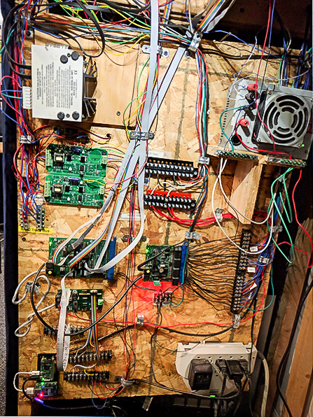
As the division AP Chair, my job is to encourage participation in the program, answer your questions, and help with your paperwork, if necessary. You can contact me at: jjclarke57@gmail.com or 301-253-4913.